
Titan RentSpray 650 Airless Paint Sprayer Parts
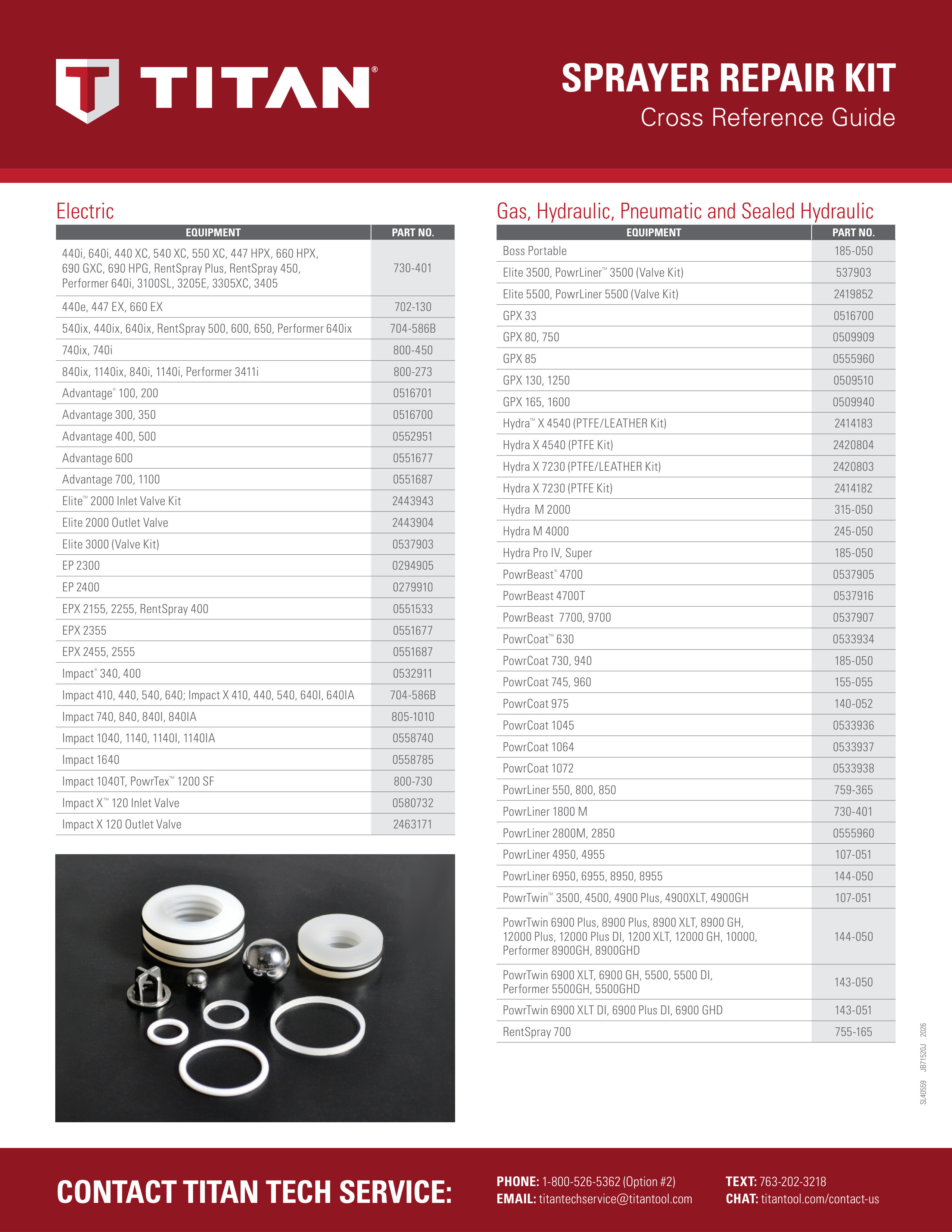
Find repair parts for the Titan RentSpray 650 using owner manual 313-2689B (0707). This manual covers models 766-4080 skid and 766-4085 High Rider. Match your model number and installed assembly before ordering.
Click a numbered marker to see matching OEM and aftermarket replacement choices. Use the zoom buttons to enlarge the drawing.
Jump to: Main Assembly · Skid / Stand Assembly · Suction Set Assembly · Fluid Section / Pump · Drive Assembly · High Rider Cart
Main Assembly
For models 766-4080 skid and 766-4085 High Rider. Cord item 4, strain relief item 12, and pump item 17 vary by configuration. Items 8 and 9 are optional Xact Digital Control components. Items 25 and 26 are not shown; cover 704-473 is for sprayers without Xact Digital Control. Match the installed model and controls.
No confirmed catalog match: Item 1 - 704-181 Screw (includes washer and grommet); Item 2 - 766-232 Motor cover; Item 5 - 704-229 Ground screw; Item 6 - 704-486 Screw; Item 7 - 704-488 Pressure control knob; Item 11 - 704-300 Siphon assembly (skid); Item 12 - 704-369 Strain relief (high rider); Item 16 - 704-470 Control panel; Item Accessory - 704-594 Surge suppressor (not shown); Item Label - 313-2688 Motor cover label; Item Label - 313-1847 Shock hazard label; Item Label - 313-2324 X-Lock label; Item Label - 313-2327 Xact Digital Control label; Item Label - 313-2328 Xact instruction label; Item Label - 313-2430 Transducer warning label.
Skid / Stand Assembly
Left leg assembly 704-179 includes items 1-4; right leg assembly 704-178 includes items 5-10. Item 2 appears twice. Compare the installed legs and hardware.
No confirmed catalog match: Item 2 - 710-199 Plug; Item 3 - 704-164 Leg, left; Item 7 - 704-244 Clip; Item 9 - 704-163 Leg, right; Item 10 - 761-188 Screw; Item Assembly - 704-178 Leg, right, complete (includes items 5–10).
Suction Set Assembly
For skid siphon assembly 704-300. Item 4 includes standard and optional solvent-resistant O-ring choices. The hose entry says it includes items 2-4 and 7, but this drawing and table have no item 7; confirm your installed assembly.
No confirmed catalog match: Item Assembly - 704-300 Complete siphon assembly.
Fluid Section / Pump
For pump 704-537 on skid models or 704-554 on High Rider models. Foot valve housing item 20 has separate skid and High Rider choices. Filter item 21 includes catalog-listed mesh choices. The manual lists filter spring 730-038 at item 24; confirm this printed reference before substituting another spring. PRIME/SPRAY valve assembly 700-258 includes items 27-31; item 28 is the complete valve stem 800-925. Piston assembly 704-552 includes items 8-13. Repacking kit 704-586 and packing tool item 32 are listed; the tool is not pictured. Follow the illustrated packing orientation.
No confirmed catalog match: Item 7 - 704-547 Lower packing assembly; Item 14 - 755-186 Piston bushing; Item 16 - 730-510 Inlet cage; Item 24 - 730-038 FIlter spring; Item Assembly - 704-552 Piston assembly (includes items 8–13).
Drive Assembly
The 650 table specifies transducer 704-492 at item 4, including O-ring item 5 (704-584); motor 704-605 at item 7; and pump housing 766-111 at item 11. Match these references to your installed unit. Jumper wire item 13 is not shown.
No confirmed catalog match: Item 5 - 704-584 Transducer o-ring; Item 7 - 704-605 Motor; Item 11 - 766-111 Pump housing; Item 12 - 700-2060 Slider assembly.
High Rider Cart
For High Rider cart assembly 704-574. Weldment item 1 includes plug item 5. Compare the frame, wheel spacers, and caps with model 766-4085.
No confirmed catalog match: Item 1 - 704-573 Cart weldment (includes item 5); Item 3 - 704-354 Spacer; Item 5 - 710-199 Plug; Item Assembly - 704-574 Complete High Rider cart assembly.