
Titan 660XC Airless Paint Sprayer Parts
Find repair parts for the Titan 660 XC using owner manual 313-1438 Rev A (1299). This manual covers models 702-2000, 702-2001, 702-2002, 702-2003, 702-2004, 702-102-CE, and 702-104-CE. Match your sprayer model, voltage, and configuration before ordering.
Click a numbered marker to see matching OEM and aftermarket replacement choices. Use the zoom buttons to enlarge a drawing.
Jump to: Main Assembly Overview · Motor Assembly · Motor Housing Assembly · Gear Box Assembly · Filter Block Assembly · Fluid Section / Pump · Suction Set Assembly · Low Rider Frame Assembly · High Rider Frame Assembly · Stand / Skid Assembly
Main Assembly Overview
Unnumbered exploded overview from the manual. Use the separate numbered assembly diagrams below to select parts. Replacement labels are listed beneath this overview when a confirmed catalog match exists.
No confirmed catalog match: Item Label - 700-1017 Replacement label (not shown in overview); Item Label - 313-175 Replacement label (not shown in overview); Item Label - 313-1436 Replacement label (not shown in overview).
Motor Assembly
Rear motor and armature components. Item 139 has 702-242 for 110V, 702-241 for 100V, and 702-243 for 230V units. Match the motor voltage before ordering.
No confirmed catalog match: Item 130 - 761-023 Screw; Item 131 - 702-046 Rear Cover; Item 136 - 702-045 Rear Motor Housing; Item 137 - 702-047 Wave Washer; Item 139 - 702-242 Armature (110V units); Item 139 - 702-241 Armature (100V units); Item 139 - 702-243 Armature (230V units).
Motor Housing Assembly
Outer housing 702-404 excludes screw 141. Field assembly item 142 has separate 110V, 100V, and 230V references. Match the installed motor voltage.
No confirmed catalog match: Item 140 - 702-404 Outer Housing (excludes 141); Item 141 - 761-244 Screw; Item 142 - 702-211 Motor Field Assembly (100V units); Item 142 - 702-137 Motor Field Assembly (230V units); Item 143 - 700-639 Screws.
Gear Box Assembly
The manual uses callouts 21-59. Cord, switch, fuse, and control-board options vary by voltage. Washer 700-688 is used at items 32 and 36; screw 21 appears three times. The front-plate entry 44 repeats label number 700-1017, so it is left unlinked pending confirmation.
No confirmed catalog match: Item 23 - 702-039 Brush Insulator; Item 24 - 765-047 Brush Gasket; Item 25 - 702-067 Brush Spring; Item 26 - 702-066 Brush; Item 30 - 702-079 Oil Seal (#028 O-Ring); Item 31 - 702-300 Motor Housing (includes items 30 and 59); Item 33 - 730-167 Output Pinion Gear Assy; Item 44 - 700-1017 Front plate (manual repeats the front cover label number; confirm correct plate before ordering); Item 46 - 765-054 Power Cord; Item 46 - 761-725 Power Cord (230V units); Item 47 - 700-645 Rubber Boot; Item 48 - 770-593 On/Off Plate (230V units); Item 50 - 700-191 In-line fuse (230V units); Item 51 - 700-895 Fuse 15 Amp; Item 53 - 700-785 Lock Washer; Item 55 - 700-162 Pressure control board (110V units); Item 59 - 702-014 Grease Seal.
Filter Block Assembly
Filter housing assembly 702-305 excludes items 212, 232, 233, and 242. Filter item 204 includes catalog-listed mesh options. Item 219 includes the standard O-ring and optional PTFE O-ring 700-897. O-ring tool 700-890 is not pictured.
No confirmed catalog match: Item 201 - 710-069 Plug; Item 207 - 702-009 Filter housing; Item 214 - 570-008 1/4” nipple; Item 218 - 700-246 Bypass housing (includes items 216 and 217)); Item 240 - 702-305 Filter housing assembly (excludes items 212, 232, 233, and 242).
Fluid Section / Pump
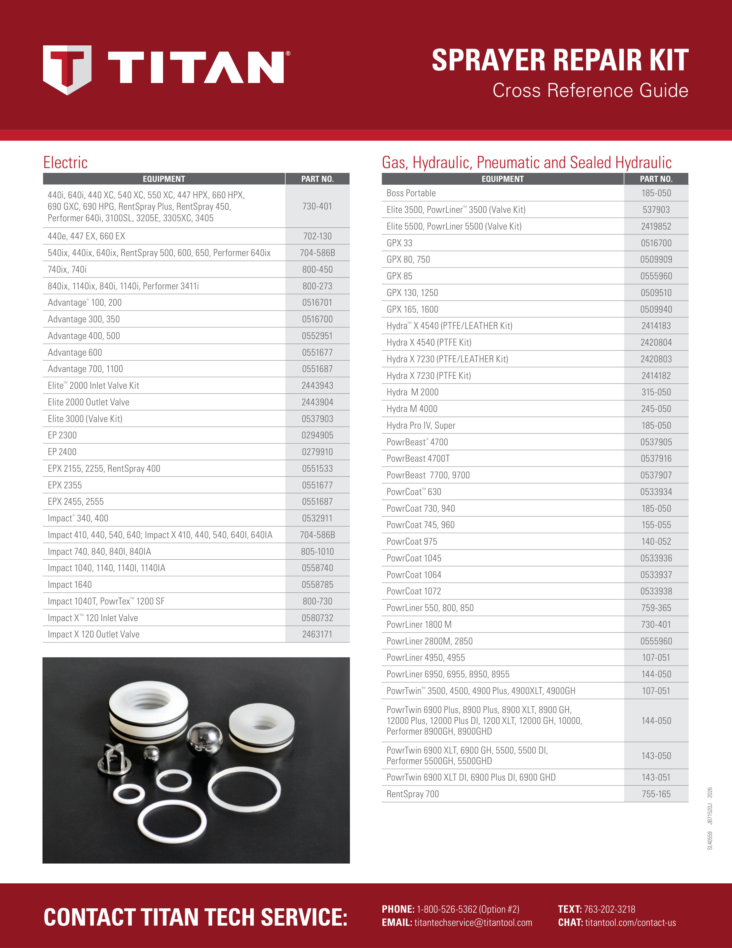
Low-rider/skid and high-rider pumps have different foot valve housings at item 323, foot valve assemblies at item 325, and complete fluid sections at item 350. Repacking kit 730-401 and high-rider-only accessories are listed after the numbered parts. Follow the manual packing orientation.
No confirmed catalog match: Item 300 - 700-735 Crank & Slide Connecting Rod Assy; Item 304 - 700-603 Upper Seal; Item 308 - 730-506 Piston Rod; Item 315 - 730-515 Piston Assembly; Item 317 - 730-509 Bushing; Item 319 - 730-510 Cage; Item 350 - 730-540 Fluid Section Complete, low rider and skid (includes #301-305, 307-323) .1; Item 350 - 765-143 Fluid Section Complete, high rider; Item High rider only - 755-109 Pail hook; Item High rider only - 765-142 Safety plate.
Suction Set Assembly
Items 1-7 form the siphon assembly. Item 3 includes the retaining-clip and alternate retaining-ring choices. Items 8-9 are for the high-rider down tube; item 9 includes standard 10-mesh and optional 30-mesh screens.
No confirmed catalog match: Item 3 - 704-129 Retaining ring (alternate, included in literature set); Item 5 - 755-135 Clip; Item 7 - 704-1025 Siphon assembly complete; Item 9 - 710-191 Inlet screen, 30 mesh (optional).
Low Rider Frame Assembly
Low-rider frame 702-060. Callouts 117-143 follow the scanned original drawing. Compare your frame and wheel hardware before ordering.
No confirmed catalog match: Item 117 - 702-057 Handle; Item 118 - 730-101 Hinge Lock; Item 119 - 702-116 Rear Cross Member; Item 120 - 700-802 Cap Nut; Item 121 - 700-801 1/4” Carriage Bolt; Item 122 - 702-127 Main Frame Right; Item 125 - 702-048 Wheel; Item 126 - 702-087 Spacer; Item 127 - 700-652 Bolt; Item 140 - 702-126 Main Frame Left; Item 141 - 710-051 Set Screw; Item 142 - 702-061 Axle; Item 143 - 702-060 “Low Rider” Frame.
High Rider Frame Assembly
High-rider frame 702-125. Main frame 702-141 includes items 8 and 9. Cord holder 700-761 and screw 700-069 are listed but not pictured.
No confirmed catalog match: Item 1 - 702-121 Handle; Item 2 - 710-020 Hinge Lock; Item 3 - 702-141 Main Frame(includes items 8 and 9); Item 4 - 710-194 Snap Ring; Item 5 - 710-044 10” Wheel; Item 7 - 700-652 Bolt; Item 8 - 710-199 Leg Plug; Item 9 - 710-198 Brace Plug; Item 10 - 702-125 High Rider Frame Complete.
Stand / Skid Assembly
For the skid version. The manual lists 704-091 at item 3 as the left leg and 704-092 at item 7 as the right leg; this naming differs from other manuals. Match the part number and installed leg before ordering.